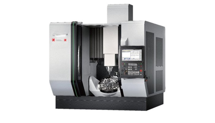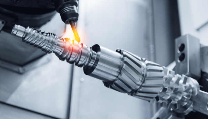
CNC milling machine is an assembly of many parts and components. Knowing every component of CNC milling machine will help you choose the right replacement part.
Additionally, this knowledge is critical when operating CNC milling machine optimally.
Remember, the number of CNC milling machine parts varies depending on the machine model and design. However, today, we will focus on the main parts of a milling machine.
What is a CNC Milling Machine?
This is a tool that is controlled using a computer. It serves for both shaping and turning a wide range of materials, including plastics, glass, metals, and wood. Like the standard lathe machines, milling machines heavily depend on computer programs that guide their operation.
Parts of a CNC Milling machine
1. Frame/Base
This component is the bedrock of this milling machine. It performs a vital role in structurally supporting the other components. This component is also vital for the overall stability of the tool, as it absorbs shock and minimizes any unnecessary movement.
It is typically made using heavy-duty, strong material that features elevated strength as well as inherent vibration-damping abilities, such as welded steel or cast iron. It functions as a mounting surface and may feature components for attachments as well as coolant channels.
2. Column
This component is composed of a straight upright structure that is placed on the base of the milling tool. The part primarily serves as a support structure for all the mobile components. The parts supported include: ram or overhanging arm, milling head, and spindle.
The internal cavity of components is often used to protect both electrical and mechanical components. Components located inside this structure include gears, lead screws, counterweights, and a spindle motor. You can also find the movement mechanism referred to as the Z–axis enclosed in this component in select designs.
3. Worktable/Bed
This is a flat surface that is key for every operation, as it provides a secure and stable surface for the workpiece to be placed on. It is typically designed using high-strength materials such as cast iron for elevated stability and to minimize vibrations. It supports the workpiece, allowing you to position and adjust the piece relative to the turning tools for a better finish.
The component features motion along the X and Y axes and, in some models, even the Z axis. To meet complex 3D processing needs. It also incorporates attachment devices such as fixtures, clamps, or vices installed into its T-slots.
4. Spindle
This is the most important part required by this tool to function. It plays the key function of supporting and manipulating the turning tools by spinning the tools at alternating speeds. This affords the machine the precision and torque it needs to perform the various operations.
This component features a tapered section that is used for mounting the various turning tools required. It is fitted to a motor, which causes it to rotate, which in turn allows the turning tool to also rotate. The speed and the path are determined by the computer program, and the position of the spindle varies depending on the machine that you have.
5. Turning Tool
This is the tool responsible for carving off the workpiece via rotating sharp components. This component determines the quality of the final product through precision. There are various types of turning tools that are designed to perform a specific function; they include;
- End Mills: They shape the workpiece by slotting, profiling, contouring, and plunging the ends as well as the sides. It comes in different shapes, including corner radius, flute counts, ball nose, and square.
- Face Mills: It features several turningteeth along a wide diameter that is ideal for designing flat surfaces
- Ball Nose Cutters: features a rounded tip better suited for 3D cuts
- Slab Mills: features sharpened peripheral edges that are used for removing large pieces of material horizontally.
- Slot Drills: designed with a pair of flutes ideal for creating sockets and pockets due to their ability to plunge cut.
Others include roughing end mills, t-slot cutters, thread mills, and specialized cutters.
6. Tool Changer/Tool Holder
This component aids in switching between tools, automating the process, making it much more efficient. The tool holder is equipped with quick-release and attachment mechanisms as well as gripping parts such as tapered fittings, chucks, or collets. You can store as many tools as will be required for your machining process in the tool magazine.
This component is fitted with a rotating arm that is attached to a spindle. The spindle helps to position the arm in its required place for tool change from the tool magazine before returning it to the working table.
7. Drive System
This system serves as both a power station as well controlling the movement of the various components. It is vital for the precise movement and position of the turning tools as well as the worktable. It is composed of AC and DC servo and stepper motors that are required for rotating movements.
This part also features other components, such as
- Ball Screws / Lead Screws, which function by producing linear motion from rotary movement
- Amplifier Circuits that rely on instructions from the CNC controller, which it then amplifies.
- Guideways that provide a table path with reduced friction
8. Linear Axes (X, Y, Z)
These axes stand for the plane of motion, along which tools and work pieces move. The axes include:
- X-axis: Located in the horizontal plane, parallel to the workpiece mounting surface and perpendicular to the Z-axis. Its motion is typically horizontal, from the operator’s left to the right.
- Y-axis: Perpendicular to the X-axis and parallel to the mounting surface, it typically moves in a forward-backward direction.
- Z-axis: Typically parallel to the spindle axis. The direction of the cutting force applied by the spindle is the Z-axis. It represents vertical motion, moving the tool or table up and down to control cutting depth.
9. Rotary Axes (A, B)
These axes provide an additional range of motion for the tool, increasing precision and efficiency. They allow the machine to rotate various components, such as the workpiece or the turning tool itself. Additional movement allows for the machining of complex or angled workpieces as well as multi-sided pieces.
- A-axis:Rotates around the X-axis (horizontally), allowing the tool or workpiece to rotate horizontally.
- B-axis: Rotates around the Y-axis (vertically), allowing the tool or workpiece to rotate vertically.
- C-axis: Rotates around the Z-axis, typically rotating around the spindle (Z-axis).
The plane of movement may vary depending on the configuration of the machine.
10. Control Unit (CNC Controller)
This component functions as the equivalent of the brain in the machine. It is responsible for all key functions performed by the machine, including its precision. It is equipped with the ability to read instructions from the program and decode them to allow for accurate movement along the different axes.
Interpolation methods are used to create motion. The component sends the required signals to the drive system and receives feedback from monitoring sensors. This feedback allows it to correct any error that occurs.
1. Input Device
This part contains the code that is required by the machine to perform its various functions. It functions as an interface linking the control unit with an external server. This component is fitted with the following features to help it perform its functions:
- Keyboard
- USB flash drive
- Wireless communication
- Older versions feature magnetic tape readers and punch tape readers
12. Electrical Cabinet
This is a storage area that encloses the circuits and other electrical components of the machine. It helps to control, coordinate, and safeguard the drive and electrical system. It is therefore required for the safety and efficiency of the operation.
It typically houses the following parts.
- Servo drives
- Relays and contactors
- Programmable logic controller
- CNC controller
- Power supply
- Inverters
- Motor drives
- Circuit breakers and fuses
- Transformers
- Cooling system
- Sensors and limit switches
13. Feed Mechanism
This component, typically situated at the knee of the tool, is an electromechanical system that is responsible for the precise movement of the turning tools. This part allows for accurate motion along the X, Y, and Z axes, aiding in the turning process.
It contains motors that read commands from the controller and determine the path required. The component then initiates the movement of the work bed that contains the piece being worked on. It also features control electronics as well as ball screws.
14. Coolant System
This is the part that is responsible for reducing the heat produced by the machining process, as well as eliminating chips and minimizing friction. It typically consists of a reservoir located at the bottom of the machine, filled with enough coolant to last the entire operation. It also features a pumping and a delivery system that allows pressurized fluid to flow through the turning tools.
It also includes other components such as
- Controller Integration that controls the cooling systems
- Nozzles and Hoses, which aid in controlling the direction of flow to ensure that all components receive the fluid
- Filters that function by separating the chips from the fluid
- The Coolant Return System guides the fluid back into its tank
15. Ram
This is the adjustable component, typically shaped like an arm, and is mainly found in select machines, such as the vertical milling machine. It is situated on top of the column and serves as support for the milling head. This component facilitates movement in and out across the work bed, allowing you to create various shapes and sizes.
This is also equipped with mounts that allow you to attach various tools. The component features a pivoting head that allows for a wider range of motion, such as nodding and tilting. It allows the tool to be repositioned when the machine is stopped or in a safe state, that is, when the tool is not being turn; with the exception of 5-axis CNC machines, the tool posture can be adjusted in real time.
16. Cantilever
This section of the machine is made up of a protruding beam that functions as support for some parts of the machine, including the spindle. It facilitates the movement of the spindle over the work table. This allows for a more efficient work process, as well as allowing the machine to operate on much larger and complex pieces.
17. Lubrication System
This section is responsible for lubricating the moving parts of the machine, reducing friction. Reduced friction, in turn, prolongs the service of the tools by minimizing wear and tear. It is composed of the following components:
- Lubricant Reservoir, which contains the lubrication fluid
- A pump that facilitates the flow of the fluid to the required components
- A distribution Network consisting of a network of tubes that provide a pathway for the fluid to flow through
- Nozzles that dispense the required amount of lubricants onto the required components
- A control system is typically integrated with the CNC to control the timing and cycles of the lubrication process
- Filters for maintaining the quality of the fluid by eliminating contaminants
18. Spindle Support
This section plays a vital supporting role, helping to not only hold but also stabilize the spindle. It is typically designed using high-strength material that provides a stable and sturdy surface for mounting other parts. It encloses the spindle bearings and may, in some cases, be included in the head of the tool.
19. Ball Screws / Linear Motors
These screws are essential for changing the rotary motion into a precise linear motion. It typically features a threaded screw and an accompanying nut with ball bearings, allowing for precise, smooth movements along the tool’s various axes. This component, with elevated mechanical efficiency and durability, helps reduce wear, prolonging the service life of the machine.
20. Human Machine Interface (HMI)
This is a component that connects the operator and the machine using a user-friendly display and control that allows the operator to communicate and set the system. The section consists of the following components.
- Operator Interaction: encompasses features that allow the operator to monitor, input commands, adjust parameters, and view real-time machine status.
- Display: used to present vital information, such as the set parameters that the machine is operating with, such as feed rates, spindle speed, and various diagnostic information.
- Programming: This part also allows you to load, edit, or remove programs from the operating system
21. Encoders
These are accuracy feedback sensors that offer real-time information on the operating parameters of the system. Factors such as direction, speed, and position of the moving parts are relayed by this section. It is essential as it ensures that the tools, workbench, and workpiece are all precisely positioned to prevent any errors during the machining process.
There are a few variants present:
- Rotary encoders
- Linear encoders
22. Machine Control Unit (MCU)
The sole role of this component is to read, interpret, and execute the instructions it gets from the machine’s program. These programs determine various factors such as spindle speed, feed rate, motors, and other supplementary components. It does this by converting the instructions into accurate electrical signals, which in turn influence the above factors.
It is also fitted with sensors that give it feedback, allowing it to detect and rectify any errors by stopping operations in addition to issuing alerts.
Auxiliary Components
These are supplementary components that are incorporated into the machine for select applications. They include;
- Bar Feeders
- Work Holding Fixtures such as magnetic chucks, clamps, and vises
- Chip Evacuation Systems, such as chip conveyors
Conclusion
There are common components that are typically featured in all CNC milling machines. These components: Worktable, Frame, Spindle, Axes, Drive System, Human Machine Interface (HMI), Electrical Cabinet, Feed Mechanism, Tool Changer and Tool Holder, Control Unit (CNC Controller/MCU), and Input Device. Different variations may feature additional components that are adapted to perform specialized functions.
FAQ
Where can you get CNC milling machine replacement parts?
You can acquire replacement components from a variety of sources, including engineering firms, select online vendors, industrial marketplaces, and machine shops.
What are the axes in a CNC milling machine?
There are two main categories of axes. The first one is the linear axes composed of X, Y, and Z axes. The second category is the rotation axes comprising A, B, and C axes.
Why is the frame or base important?
This component is essentially the foundation of the entire machine, providing both structural and operational support.
Can CNC milling machines operate with multiple axes?
Yes, it is indeed possible for you to operate this machine on multiple axes.
Related resources:
Types of Milling Machines – Source: Shawahed
High Precision CNC Milling Machine – Source: Shawahed
CNC Programming – Source: Audodesk